
Property 01
Rigid mass
High mass is concentrated in a stiff, non-compliant form.
Layer 1 · Engineering Authority · PSC Hand Safety
The definitive engineering reference for selecting and applying the correct guidance method when ferrous loads must be lifted, positioned, and aligned. Not a product catalogue — a technical framework.
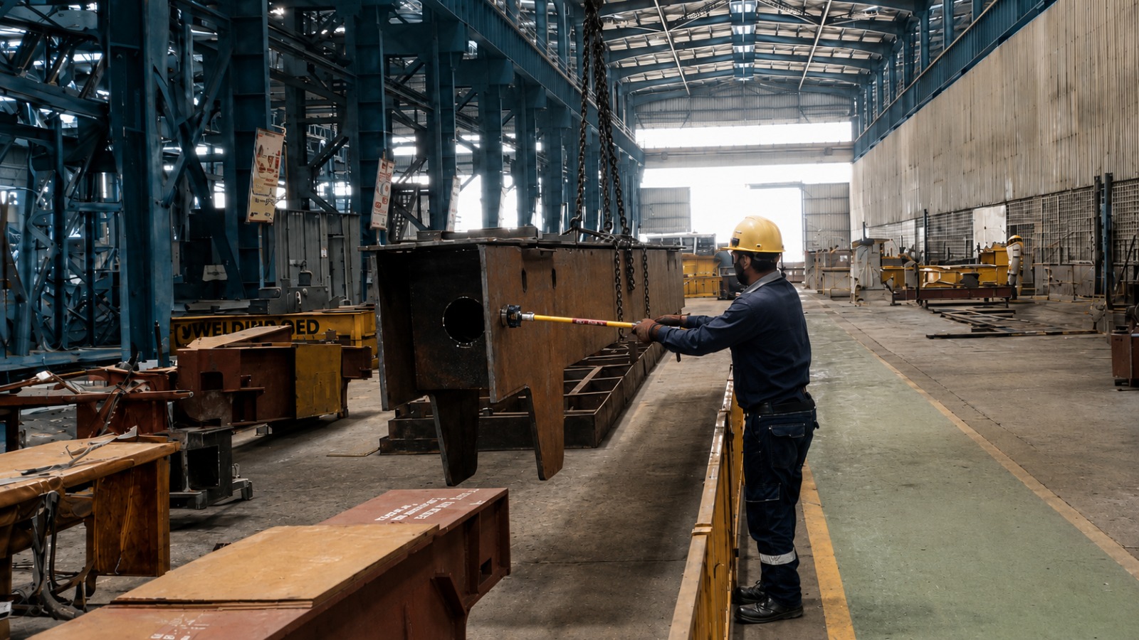
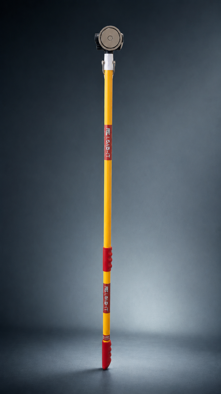
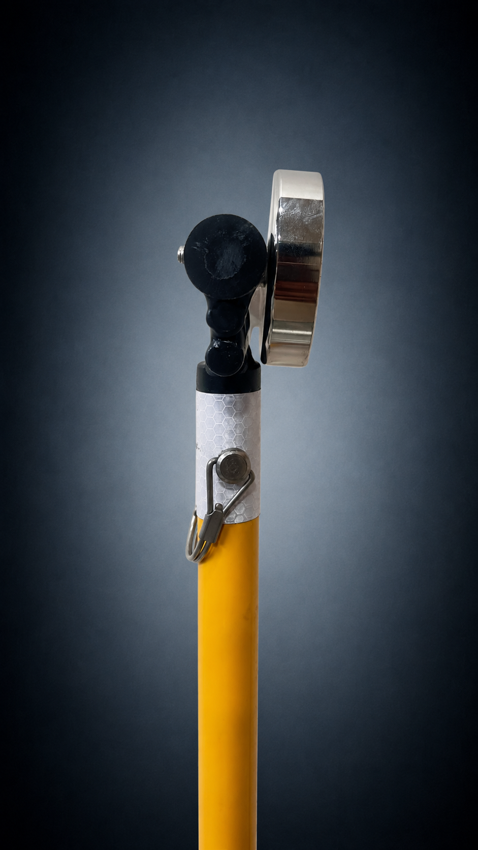
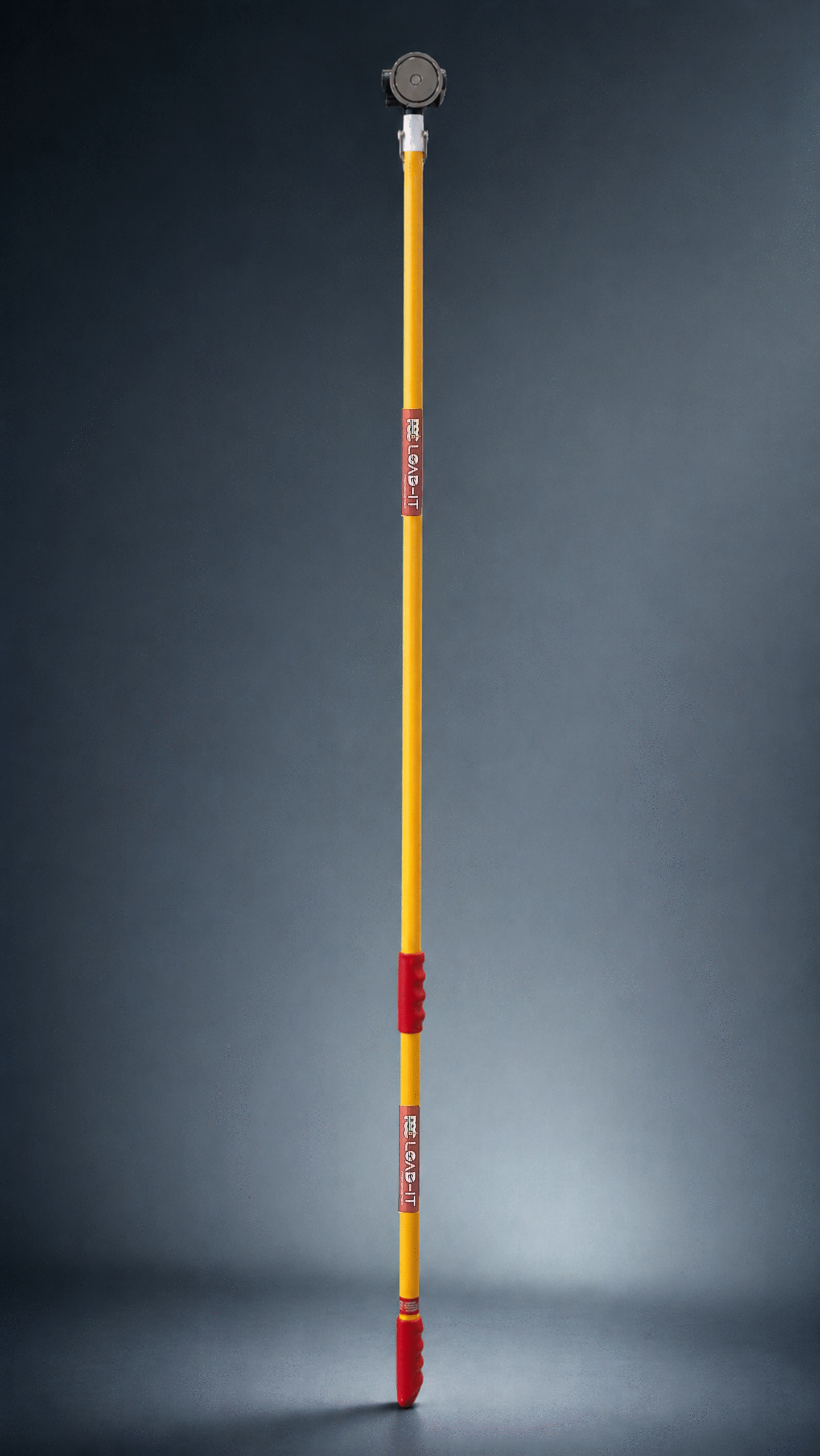
Why Ferrous Loads Create a Distinct Positioning Challenge
Most discussions of load positioning begin with the equipment. This guide begins differently — with the problem. A suspended steel load is not a passive object waiting to be moved into place. It is a physical system with its own momentum, its own centre of gravity, and its own tendency to rotate, drift, and swing. Understanding that behaviour is the prerequisite for selecting any engineering control.
Steel loads behave differently from palletised loads, containerised units, or fabric-slung materials — largely because of three combined properties: mass concentrated in a rigid form, a high centre of gravity relative to a limited suspension point, and surface geometry that frequently offers no safe handholds.
These properties apply across steel plates, H-beams, structural assemblies, motors and machine components, and fabricated sub-assemblies. In every case, the load requires correction during positioning. It does not arrive at its final location purely through the lifting action. Someone — or something — must apply a final, controlled, directional force to bring it into alignment.
High mass is concentrated in a stiff, non-compliant form.
The centre of gravity must settle beneath a limited suspension point.
Steel surfaces frequently provide no safe direct hand interface.
The Physics Behind Suspended Load Behaviour
Pendulum motion explains lateral swing. Centre-of-gravity offset explains settling angle. Rotational inertia explains turning. Together, they explain why the positioning phase requires its own engineering controls — separate from the lifting plan that governs the lift itself.
Where the Hand Exposure Actually Lives
The highest hand exposure during load handling does not occur during the lift itself. It occurs during the final positioning phase — the moments when the crane has done its job and the worker must steady, rotate, align, and seat the load.
The Last 300 mm Rule™ captures this precisely: the crane closes the major distance; the last 300 mm — where the component is guided into its final position — belongs to the worker standing closest to the steel.
| Exposure Type | Description | Typical Task Context |
|---|---|---|
| Pinch Points | Hand caught between the load and a fixed or secondary moving surface | Guiding a plate toward a rack or frame |
| Crush Points | Hand or fingers trapped under load weight as it settles | Final placement onto a base or mounting surface |
| Swing Paths | Hand positioned within the arc of a pendulum-style movement | Steadying a beam from a single suspension point |
| Line-of-Fire | Body in the direct path of load travel if released or if rigging fails | Reaching between load and structure during alignment |
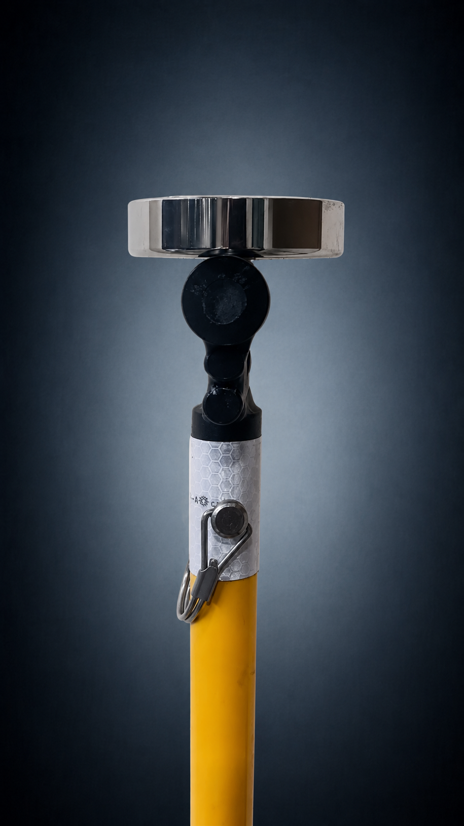
The Five Guidance Methods — and How to Choose
Not every hand-intensive load task calls for the same engineering control. Five hands-free or reduced-contact methods cover most industrial guidance and positioning work.
Sustained, repositionable engagement on ferrous loads with viable surfaces.
Requires ferrous material and suitable surface condition.
Non-ferrous and coated surfaces; stable flat contact face.
Requires a stable flat contact face.
Structural edges, flanges and lips.
Limited use on flat, featureless surfaces.
Rigging-point handling, independent of surface condition.
Requires an existing engagement point.
Gross swing and orientation control across a wide range of motion.
Coarse control only; not suited to fine close-range positioning.
The Decision Path
A magnetic push-pull tool is the correct choice when the load is ferrous, a viable flat or gently curved attachment surface exists, and the task requires sustained, repositionable engagement.
Where any condition is not met, a mechanical contact method or tagline is likely more appropriate. PSC publishes this decision logic openly — a correctly selected alternative is more valuable than a magnetic tool used on the wrong application.
PSC Engineering Principle
“A magnet on a pole is easy to compare on price. An engineered hands-free method should be compared on the application.”
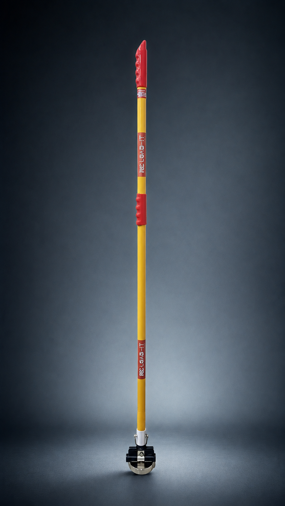
Premium Engineering Consultation
PSC's Application Mapping Review examines the actual task — the load, the surface, the access conditions, and the operator's movement — and recommends the correct matched configuration.